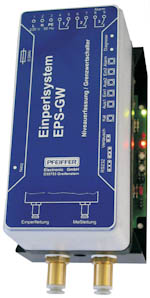
Bubbling System EPS-GW
The pneumatic level sensing EPS converts air pressure generated by the hydrostatic backpressure of the water level to a proportional, standard electrical signal. It is possible to correct the zero reference point and scaling using a single button. LEDs indicate false settings as well as system errors.
The compressor is operated alternately with a duty cycle of approx. 20%. Optionally, it is possible to automatically test the performance of the compressor daily utilizing a test programme. A fault alarm is issued if performance characteristics deviate.
The bubble tube can be installed in potentially explosive atmospheres.
A bubble tube and measurement lead are routed separately to prevent condensation forming (devices with two pneumatic connections).
Mounting/installation
The EPS bubbling system is designed to be mounted straight onto a mounting plate in a switchgear cabinet with an appropriate IP rating. Route pneumatic line(s) to the bubble tube with a downward gradient and protect from frost. These lines can be up to approx. 50 m in length. The bottom edge of the bubble tube corresponds to the zero reference point of the system.
EPS with one pneumatic connection
With this solution the measurement lead (sensor) and the pressure line (compressor) are connected inside the device by means of a T-piece. The pneumatic line alone is routed to the measurement point.
EPS with two pneumatic connections
The measurement lead (sensor) and pressure line (compressor) are routed separately to the measurement point.
EPS with automatic performance test
The compressor line is tested automatically every 24 hours. To test the performance of the compressor immediately simply press the “Test” button. The fault relay is activated if the compressor no longer achieves the required performance. The message remains stored even after the device has been switch off and on again. To reset the message simply press the “Test” button.
Zero reference point / full scale value
The device is preset ex works. Proceed as follows to alter or correct the values:
Zero reference point
Depressurize the system before setting the zero reference point! Then press the “KAL” button. The lower LED flashes to acknowledge when the setting has been successfully applied. The analogue output accepts the smallest value (0 or 4 mA).
It is possible to raise the output value from 0 to 4 mA (for open-circuit monitoring purposes).
Full scale
To set the full scale value, apply the desired full-scale value to the system (e. g., 2.0 mwc) and press the “KAL” button as above. And as above, the lower LED flashes to acknowledge the setting has been successfully applied. The analogue output accepts the largest value (20 mA). Important: the full scale should equal at least 40% of the possible measurement range. The device does not accept too low pressures.
The preset factory setting is the max. measurement range. It is equally possible to reconstruct this setting using a jumper. To do so, isolate the device from the power supply. Set the jumper to the “Werk” (factory) setting and then restore the power supply. The device will restore factory settings and operate accordingly. Then remove the jumper.
Flash code - diagnostics LED
Lower LED flashes: Setting successfully applied.
Upper LED flashes: Pressure is applied to the measurement system (the flashing frequency increases as the pressure increases).
Upper LED is off, the lower LED is on: Zero reference point reached (system is depressurized).
Upper and lower LEDs flash alternately: Parameters could not be applied (after pressing the button) or error message issued by system monitoring function (without previously pressing the “KAL”) button.
Technical data
| Measurement ranges |
0... 2.5 / 4.0 mwc /10.0 mwc |
| Operation voltage | 230 V / 50 Hz |
| Power consumption | Approx. 7 |
| Overload | bis 3-facher MessbereichUp to 3x the measurement range |
| Relais-Ausgang | 250 VAC, 5A max. 200 VA |
| Compressor | Polycarbonat |
| Hose connection | 8 mm outside diameter |
| Housing | Galvanized sheet steel / polycarbonate |
| Diagnostic interface | RS 232 |
| Degree of protection | IP 00 |
| EMCEmission/EMCImmunity | EN 50 081-2, EN 50 082-2 |