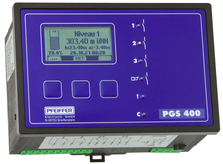
Water Management Controller PGS 400-2K
The PGS 400 controller is deployed together with one or two sensors capable of supplying standard 0 or 4-20 mA current signals (e.g. submersible transmitters ETG) as a versatile, intelligent decentralised control solution designed for use in all areas of drinking water and waste water technology – in applications that require water levels, pressure or flow rate to be determined and recorded simply and precisely with high levels of operational reliability.
The PGS 400 controller assigns the standard current signal 0 / 4...20 mA supplied by the sensor to a level expressed in the unit mWS (bar for pressure measurements and l/s for flow rate measurements).
Scaling, e.g. of level measurements, is optionally calibrated via the maximum value of the sensor at 20 mA or the actual measured value (instantaneous value).Level scaling is fixed in 1/10, 1/100, or 1/1000 steps.
The displayed value is calculated according to the input current and the fixed scaling factor.
In addition, it is also possible to scale a percentage display. The value of the analogue output changes in line with this scaling, with 100 % corresponding to 20 mA at the output.
It is possible to determine all limit values via the measurement range. The switch-on value of all three limit value pairs can be above or below the switch-off value (fill or empty tanks). Cyclical alternating of two or three limit value contacts balances the load of the connected pumps to ensure uniform wear.
Uninterrupted monitoring of the measurement system facilitates a high level of operational reliability.
Fault states – wire breaks or short-circuits – corresponding to falling below the programmed zero point or exceeding the permitted input current are displayed in clear text as well as indicated as a potential-free fault signal.
For user convenience it is possible to configure all functions in a menu-assisted environment using just three buttons – eliminating the need for an additional programming device.
A separate DC voltage source supplies the requisite auxiliary power supply to the sensor.
Features
General:
- Graphic display for measurement values
- Clear text display of system status and configuration
- Intuitive, menu-assisted operation
- Integrated auxiliary power source
- 2 analogue inputs 0/4... 20 mA
- 2 analogue outputs 0/4... 20 mA
- 4 relay outputs
- Max./min. value recording (indicator) including time stamp
- Uninterrupted monitoring of measurement system
- Retains parameter settings if the mains power supply should fail (EEPROM)
- Fault messages logged
- Integrated data logger including SD card and archiving function (optional)
- Mounts in front panel or onto mounting plate (DIN top-hat rails)
- Membrane keypad and lockable front panel
Limit values/scaling:
- User selectable units, for example mWS, bar and l/s
- Precision set limit values
- Optional user adjustable scaling of the final value or the actual value (instantaneous value) in the respective unit
- Percent value scaling
- User-definable zero point
- Programmable opening and closing of contacts
- LEDs indicate control state of the relays
- Optional alternating operation (cyclical or operating hours) of the limit value contacts
Control and timer functions:
- Level and trend recognition combinable with a limit contact
- Operating hours counter of relay outputs
- Pump start counter (number of start commands)
- On and OFF delay
- Runtime monitoring of relay outputs
- Forced relay outputs
- Maintenance intervals indicated for relay outputs
Technical data
| Degree of protection | Front: IP 54 |
| Material | Kunststoff, ABS |
Memory
| Parameters | EEPROM |
| Data / measurement | SD-Card (Option) |
Total error
| Measurement accuracy | < +/- 1 |
Display
| Display | Grafische LCD, 128x64 Punkte hinterleuchtet |
| Update measured value | alle 2 s |
| Display area | 0 ... 999999 |
| Unit | wählbar |
| Percentage display | 0 ... 999,9 |
| Dämpfung | In 15 Stufen wählbar |
Output
| Contacts | 3 Schließer, 1 Wechsler, "Störung" |
| Switching capacity | 250 V/50 Hz, 2A max 200 VA |
| Number | 0/4... 20mA, Bürde max. 500 Ω |
| D/A-transformer | 12 |
Input
| Number | 4... 20 mA (aktiv) oder 0/4... 20 mA (passiv) |
| Input resistance | |
| A/D-transformer | |
| 3 dB Grenzfrequenz | 21 |
Power supply
| Operating voltage | 230 V / 50Hz oder 24 V/DC, je nach Gerätetyp |
| Power consumption | ca. 8 |
| Integrated help energy source | 24 V DC max 50 mA |